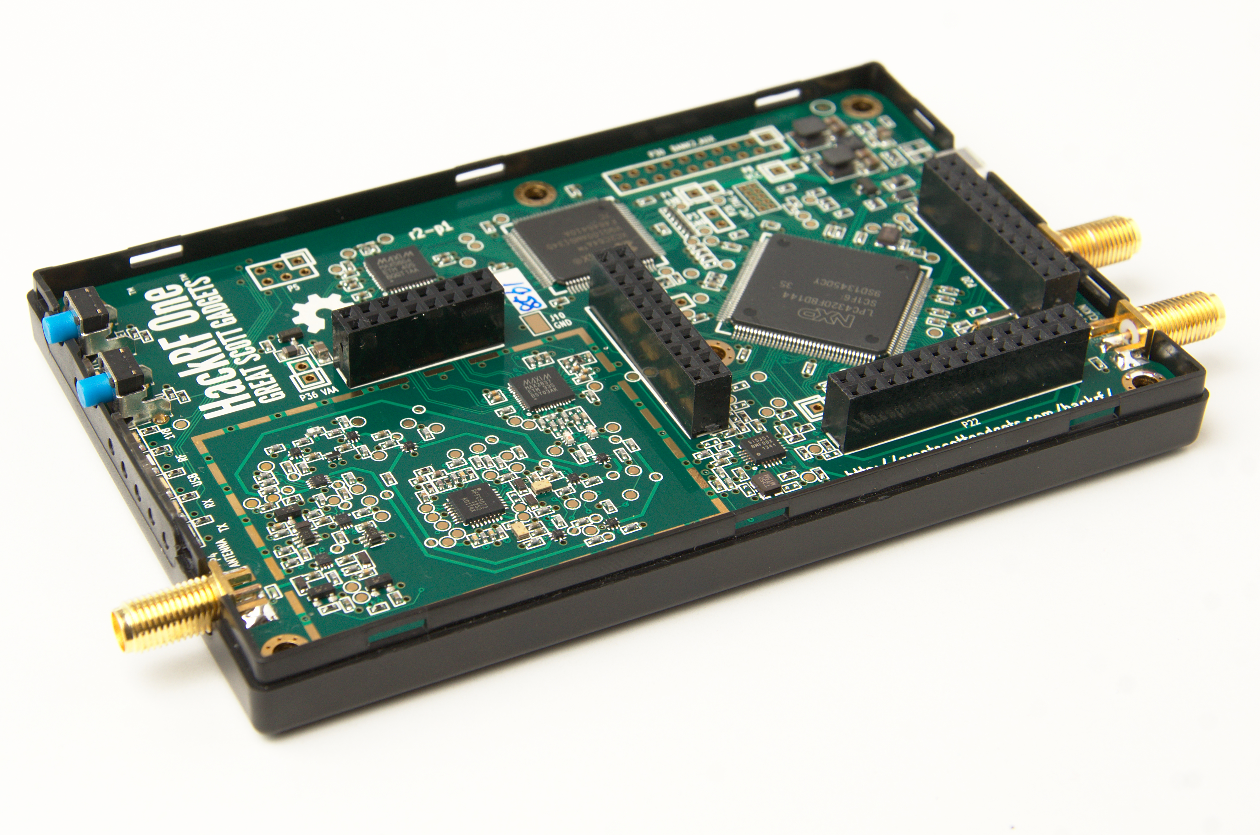
Question 1: There are three multiplexed ADC channels in the Airspy, is there a simple way to access the other two if I wanted to implement a custom DDC firmware?
Answer 1: .By default channel 0 is used for the R820T2, but channel 1 and channel 2
are unconnected. You could hack the firmware source code and modify
this line "#define DEFAULT_ADCHS_CHAN (0)" in
"firmware/airspy_m4/airspy_m4.c" to use channel 1 or channel 2 instead
of channel 0 which is connected to the output of the R820T2 tuner chip.
Of course the R820T2 would still be powered on so you should disable it,
since you are not using it (use disable_r820t_power() anywhere where
enable_r820t_power() is called) because it may add unwanted noise. Of course disabling the R820T2 chip, also means that you should
delete/disable any calls to set registers in it, since you are not be
using it. You should also delete/disable the frequency tuning from the firmware since the tuner is not used. And by the time you have done that it might be easier just to
write your own custom firmware.
Extra info 1: Since the spyverter is now available it might be easier just to use it unless you actually need an ADC, that in theory could run at 80MSPS. The problem is that the USB bus will limit the data transfer to about 20MSPS. And there is not enough RAM in the LPC4370 to buffer more than about 2x16KiB (double buffering) or 32KiB of data, and there is not enough processing power within the CPU to reduce this data. So unless 32KiB of data sampled at 80MSPS is enough for your function this is probably a dead end for your idea. If you are still going to use the two ADC ports the good news is that there is ESD protection in the R2 board, the R0 board had no ESD protection on the ADC inputs.
Showing posts with label solution. Show all posts
Sunday, 29 November 2015
Monday, 2 March 2015
How to use Kal software to workout the PPM frequency offset of a RTL-SDR
The basic idea behind the Kalibrate software is that a GSM mobile phone base station has an expensive very high precision atomic clock (0.01ppb), where as a RTL-SDR stick has a cheap low precision 28.8MHz quartz crystal (+/-100ppm). This cheap low precision oscillator is used to derive all frequencies when you tune the RTL-SDR, so the bigger the errors the more you are offset from the correct frequency. There are two pieces of good news the offset is linear and once the cheap crystal has warmed up it generally does not drift very much. Because the error is linear across the whole frequency range, only one correction value is required.
When you buy a 28.8MHz quartz crystal in a can, they are generally not 28,800,000Hz. There are two problems that need to be compensated for by the PPM offset in SDR receiver software. The first is manufacturing tolerance, generally about 100 PPM (0.01%) is the range to keep costs down, so the frequency of a new quartz crystal could be anywhere between 28,797,120Hz and 28,802,880Hz at 20 degrees Celsius. The second problem is that the frequency will change slightly as the device warms up. But the good news is once the device has warmed up it will not drift much, unless the ambient room temperature varies.
So basically you scan the local area for active GSM base station channels with a large amount of power (good signal strength, which will probably be from the base station that is physically closest to your current location). Then kal uses this channels GSM frequency correction bursts to workout the PPM (part per million) offset of the RTL-SDR that you are currently calibrating.
$ git clone https://github.com/steve-m/kalibrate-rtl
$ cd kalibrate-rtl
$ ./bootstrap && CXXFLAGS='-W -Wall -O3'
$ ./configure
$ make
$ sudo make install
(confirm that the RTL-SDR is actually plugged into the Linux machine)
$ lsusb | grep -i RTL
Bus 004 Device 015: ID 0bda:2838 Realtek Semiconductor Corp. RTL2838 DVB-T
(print the help for the kal software to see what arguments should be used)
$ kal
error: must enter channel or frequency
kalibrate v0.4.1-rtl, Copyright (c) 2010, Joshua Lackey
modified for use with rtl-sdr devices, Copyright (c) 2012, Steve Markgraf
Usage:
GSM Base Station Scan:
kal <-s band indicator> [options]
Clock Offset Calculation:
kal <-f frequency | -c channel> [options]
Where options are:
-s band to scan (GSM850, GSM-R, GSM900, EGSM, DCS, PCS)
-f frequency of nearby GSM base station
-c channel of nearby GSM base station
-b band indicator (GSM850, GSM-R, GSM900, EGSM, DCS, PCS)
-g gain in dB
-d rtl-sdr device index
-e initial frequency error in ppm
-v verbose
-D enable debug messages
-h help
$
$ date ; kal -s GSM850 ; date
Mon Mar 2 16:05:26 CET 2015
Found 1 device(s):
0: Generic RTL2832U OEM
Using device 0: Generic RTL2832U OEM
Found Rafael Micro R820T tuner
Exact sample rate is: 270833.002142 Hz
kal: Scanning for GSM-850 base stations.
GSM-850:
Mon Mar 2 16:08:44 CET 2015
$ date ; kal -s GSM-R ; date
Mon Mar 2 16:16:37 CET 2015
Found 1 device(s):
0: Generic RTL2832U OEM
Using device 0: Generic RTL2832U OEM
Found Rafael Micro R820T tuner
Exact sample rate is: 270833.002142 Hz
kal: Scanning for GSM-R-900 base stations.
GSM-R-900:
Mon Mar 2 16:17:09 CET 2015
$ date ; kal -s GSM900 ; date
Mon Mar 2 16:19:42 CET2015
Found 1 device(s):
0: Generic RTL2832U OEM
Using device 0: Generic RTL2832U OEM
Found Rafael Micro R820T tuner
Exact sample rate is: 270833.002142 Hz
kal: Scanning for GSM-900 base stations.
GSM-900:
chan: 9 (936.8MHz + 22.294kHz) power: 52744.70
chan: 11 (937.2MHz + 22.198kHz) power: 148897.40
chan: 48 (944.6MHz + 21.298kHz) power: 64839.80
chan: 50 (945.0MHz + 21.360kHz) power: 76421.47
chan: 66 (948.2MHz + 21.020kHz) power: 100342.53
chan: 68 (948.6MHz + 21.109kHz) power: 148650.05
chan: 74 (949.8MHz + 21.369kHz) power: 57399.97
Mon Mar 2 16:23:30 CET 2015
$ date ; kal -s EGSM ; date
Mon Mar 2 16:24:36 CET 2015
Found 1 device(s):
0: Generic RTL2832U OEM
Using device 0: Generic RTL2832U OEM
Found Rafael Micro R820T tuner
Exact sample rate is: 270833.002142 Hz
kal: Scanning for E-GSM-900 base stations.
E-GSM-900:
chan: 9 (936.8MHz + 22.059kHz) power: 55782.16
chan: 11 (937.2MHz + 22.136kHz) power: 141612.90
chan: 48 (944.6MHz + 21.194kHz) power: 60347.62
chan: 49 (944.8MHz + 20.859kHz) power: 52131.68
chan: 50 (945.0MHz + 21.268kHz) power: 79892.10
chan: 66 (948.2MHz + 21.026kHz) power: 95478.05
chan: 68 (948.6MHz + 21.074kHz) power: 142679.30
chan: 74 (949.8MHz + 21.314kHz) power: 73531.29
chan: 985 (927.2MHz + 23.002kHz) power: 79791.55
chan: 988 (927.8MHz + 22.555kHz) power: 64283.53
chan: 992 (928.6MHz + 21.866kHz) power: 57287.97
chan: 1000 (930.2MHz + 22.159kHz) power: 192336.94
Mon Mar 2 16:29:38 CET 2015
$
$ date ; kal -c 1000 ; date
Mon Mar 2 16:37:01 CET 2015
Found 1 device(s):
0: Generic RTL2832U OEM
Using device 0: Generic RTL2832U OEM
Found Rafael Micro R820T tuner
Exact sample rate is: 270833.002142 Hz
kal: Calculating clock frequency offset.
Using E-GSM-900 channel 1000 (930.2MHz)
average [min, max] (range, stddev)
+ 22.137kHz [22112, 22160] (49, 13.404841)
overruns: 0
not found: 0
average absolute error: -23.798 ppm
Mon Mar 2 16:37:23 CET 2015
$
Since there where no overruns and the signal was found every time I know that this is a good result, that I can confidently use this value with this particular RTL-SDR hardware in GRC or SDRSharp. I would round this number and use a PPM offset of -24 (0.0024%), since none of the software supports PPB corrections (yet). Even if there were 1 to 2 overruns or 1 to 5 not-found the PPM value would still probably be valid, it just meant that there was interference during the test or the signal strength of the channel used was not high enough, maybe try the test again using a different channel, that has more power (or less interference).
The Kalibrate software actually uses the GSM signals own inbuilt frequency correction bursts, that are used by mobile phone handsets (which also have cheap quartz crystals inside them) to calculate their ppm frequency correction. The original open source software was written for the Ettus Research USRP hardware and was ported work with the RTL-SDR.
When you buy a 28.8MHz quartz crystal in a can, they are generally not 28,800,000Hz. There are two problems that need to be compensated for by the PPM offset in SDR receiver software. The first is manufacturing tolerance, generally about 100 PPM (0.01%) is the range to keep costs down, so the frequency of a new quartz crystal could be anywhere between 28,797,120Hz and 28,802,880Hz at 20 degrees Celsius. The second problem is that the frequency will change slightly as the device warms up. But the good news is once the device has warmed up it will not drift much, unless the ambient room temperature varies.
So basically you scan the local area for active GSM base station channels with a large amount of power (good signal strength, which will probably be from the base station that is physically closest to your current location). Then kal uses this channels GSM frequency correction bursts to workout the PPM (part per million) offset of the RTL-SDR that you are currently calibrating.
Download, compile and install the kal software
$ sudo apt-get install libtool autoconf automake libfftw3-dev$ git clone https://github.com/steve-m/kalibrate-rtl
$ cd kalibrate-rtl
$ ./bootstrap && CXXFLAGS='-W -Wall -O3'
$ ./configure
$ make
$ sudo make install
Use the kal software to scan GSM base stations for channels with high power
My RTL-SDR only goes from 24MHz to 1750MHz, so I can not use the DCS or PCS GSM system, even if they were active in my area. I know that EGSM is active where I am, but I'll test all the frequencies to time and show how long a scans takes when no GSM is present, as well as how long it takes when GSM base stations are present (about 2-10 minutes). This will also provide the warm up time of about 10 minutes for my RTL-SDR to reach its steady state operating temperature. Some of the GSM down link frequencies are used to send the frequency correction bursts, to calibrate mobile phone handsets, so that the phones know the correction offset to use when TX'ing on the up link frequencies. This allows mobile phone makers to use cheaper hardware in their handsets, and if you are making a few billion of them small savings quickly add up to more profit..- GSM850 UPLINK: 824.2- 849.2MHz DOWNLINK: 869.2- 894.2MHz
- GSM-R UPLINK: 876.0- 915.0MHz DOWNLINK: 921.0- 960.0MHz
- GSM900 UPLINK: 890.0- 915.0MHz DOWNLINK: 935.0- 960.0MHz
- EGSM UPLINK: 880.0- 915.0MHz DOWNLINK: 925.0- 960.0MHz
- DCS UPLINK: 1710.2-1784.8MHz DOWNLINK: 1805.2-1879.8MHz
- PCS UPLINK: 1850.2-1909.8MHz DOWNLINK: 1930.2-1989.8MHz
(confirm that the RTL-SDR is actually plugged into the Linux machine)
$ lsusb | grep -i RTL
Bus 004 Device 015: ID 0bda:2838 Realtek Semiconductor Corp. RTL2838 DVB-T
(print the help for the kal software to see what arguments should be used)
$ kal
error: must enter channel or frequency
kalibrate v0.4.1-rtl, Copyright (c) 2010, Joshua Lackey
modified for use with rtl-sdr devices, Copyright (c) 2012, Steve Markgraf
Usage:
GSM Base Station Scan:
kal <-s band indicator> [options]
Clock Offset Calculation:
kal <-f frequency | -c channel> [options]
Where options are:
-s band to scan (GSM850, GSM-R, GSM900, EGSM, DCS, PCS)
-f frequency of nearby GSM base station
-c channel of nearby GSM base station
-b band indicator (GSM850, GSM-R, GSM900, EGSM, DCS, PCS)
-g gain in dB
-d rtl-sdr device index
-e initial frequency error in ppm
-v verbose
-D enable debug messages
-h help
$
$ date ; kal -s GSM850 ; date
Mon Mar 2 16:05:26 CET 2015
Found 1 device(s):
0: Generic RTL2832U OEM
Using device 0: Generic RTL2832U OEM
Found Rafael Micro R820T tuner
Exact sample rate is: 270833.002142 Hz
kal: Scanning for GSM-850 base stations.
GSM-850:
Mon Mar 2 16:08:44 CET 2015
$ date ; kal -s GSM-R ; date
Mon Mar 2 16:16:37 CET 2015
Found 1 device(s):
0: Generic RTL2832U OEM
Using device 0: Generic RTL2832U OEM
Found Rafael Micro R820T tuner
Exact sample rate is: 270833.002142 Hz
kal: Scanning for GSM-R-900 base stations.
GSM-R-900:
Mon Mar 2 16:17:09 CET 2015
$ date ; kal -s GSM900 ; date
Mon Mar 2 16:19:42 CET2015
Found 1 device(s):
0: Generic RTL2832U OEM
Using device 0: Generic RTL2832U OEM
Found Rafael Micro R820T tuner
Exact sample rate is: 270833.002142 Hz
kal: Scanning for GSM-900 base stations.
GSM-900:
chan: 9 (936.8MHz + 22.294kHz) power: 52744.70
chan: 11 (937.2MHz + 22.198kHz) power: 148897.40
chan: 48 (944.6MHz + 21.298kHz) power: 64839.80
chan: 50 (945.0MHz + 21.360kHz) power: 76421.47
chan: 66 (948.2MHz + 21.020kHz) power: 100342.53
chan: 68 (948.6MHz + 21.109kHz) power: 148650.05
chan: 74 (949.8MHz + 21.369kHz) power: 57399.97
Mon Mar 2 16:23:30 CET 2015
$ date ; kal -s EGSM ; date
Mon Mar 2 16:24:36 CET 2015
Found 1 device(s):
0: Generic RTL2832U OEM
Using device 0: Generic RTL2832U OEM
Found Rafael Micro R820T tuner
Exact sample rate is: 270833.002142 Hz
kal: Scanning for E-GSM-900 base stations.
E-GSM-900:
chan: 9 (936.8MHz + 22.059kHz) power: 55782.16
chan: 11 (937.2MHz + 22.136kHz) power: 141612.90
chan: 48 (944.6MHz + 21.194kHz) power: 60347.62
chan: 49 (944.8MHz + 20.859kHz) power: 52131.68
chan: 50 (945.0MHz + 21.268kHz) power: 79892.10
chan: 66 (948.2MHz + 21.026kHz) power: 95478.05
chan: 68 (948.6MHz + 21.074kHz) power: 142679.30
chan: 74 (949.8MHz + 21.314kHz) power: 73531.29
chan: 985 (927.2MHz + 23.002kHz) power: 79791.55
chan: 988 (927.8MHz + 22.555kHz) power: 64283.53
chan: 992 (928.6MHz + 21.866kHz) power: 57287.97
chan: 1000 (930.2MHz + 22.159kHz) power: 192336.94
Mon Mar 2 16:29:38 CET 2015
$
Use the kal software to calculate the PPM clock offset of a RTL-SDR.
So now that I have at least one channel number, with a high broadcast power in my region, I can calculate the PPM offset with the kal software (best if the RTL-SDR has had a chance to warm up, the cheap 28.8MHz quartz crystal probably drifts most with temperature).$ date ; kal -c 1000 ; date
Mon Mar 2 16:37:01 CET 2015
Found 1 device(s):
0: Generic RTL2832U OEM
Using device 0: Generic RTL2832U OEM
Found Rafael Micro R820T tuner
Exact sample rate is: 270833.002142 Hz
kal: Calculating clock frequency offset.
Using E-GSM-900 channel 1000 (930.2MHz)
average [min, max] (range, stddev)
+ 22.137kHz [22112, 22160] (49, 13.404841)
overruns: 0
not found: 0
average absolute error: -23.798 ppm
Mon Mar 2 16:37:23 CET 2015
$
Since there where no overruns and the signal was found every time I know that this is a good result, that I can confidently use this value with this particular RTL-SDR hardware in GRC or SDRSharp. I would round this number and use a PPM offset of -24 (0.0024%), since none of the software supports PPB corrections (yet). Even if there were 1 to 2 overruns or 1 to 5 not-found the PPM value would still probably be valid, it just meant that there was interference during the test or the signal strength of the channel used was not high enough, maybe try the test again using a different channel, that has more power (or less interference).
The Kalibrate software actually uses the GSM signals own inbuilt frequency correction bursts, that are used by mobile phone handsets (which also have cheap quartz crystals inside them) to calculate their ppm frequency correction. The original open source software was written for the Ettus Research USRP hardware and was ported work with the RTL-SDR.
Wednesday, 29 October 2014
Part One: Airspy NOS - Questions and Answers
Today (2014-10-29) the Airspy, was available for pre-order. And I thought that I would do the same thing that I did for the HackRF One. That I would try and keep a track of any questions that I see asked on IRC and the answers given.I though that I would make a quick log of the problems, queries along with their corresponding solutions and suggestions. And add a few extra notes of my own, if I am able. I have removed all sources of questions and answers to protect peoples privacy (what little is left of it these days).
If you are currently scratching your head, because you have never heard of an Airspy before, then you should probably go to the Airspy website.
I'll probably sort these random questions and answers into some sort of logical order when there is enough of them, Hardware, Software, GNU Radio, RF fundamentals, .... but for now I'll just leave them mixed up higgledy-piggledy in the order that I saw them asked.
Question 1: "External clock input (10 MHz to 100 MHz via MCX connector) – Ideal for phase coherent radios” what is the expected voltage ?
Answer 1: The Clock Input for the Airspy is described on page 5 of the of Si5351C datasheet.
It is 3.3v CMOS voltage levels so, low is below 0.8v (min -0.1v) and high is over 2.0v (max 3.6v). So either a square wave or sine wave that meets this criteria. Almost anything will drive it if the voltage is less than 3.6 V P-P and more than about 2.5 V P-P if it is applied to the CLKIN pin with a series capacitor, a 100k to ground, and a roughly 100k to 3.3 volts.
Extra info 1: So a 0v to 3v square/sine wave at 10MHz would tick all the boxes, and be a good clock source. The Airspy already has a pretty good crystal in it, a 1.5 ppm, low phase noise clock. It may not be perfect for some things but it is a good clock.
Question 2: "Airspy NOS R0 03 Aug 2014" is written on the PCB silkscreen, what exactly does NOS stand for ?
Answer 2: Nest of Spies.
Question 3: What is the input impedance of the Airspy SMA antenna port ?
Answer 3: 50 ohms
Question 4: What is maximum current that the "4.5v Bias-Tee to pwoer LNA’s and up/down-converters" can use ?
Answer 4: USB 2.0 provides a maximum of 500mA at 5 volts. The Airspy uses less than 400mA at 5 volts (2W), so that would mean that at 4.5 volts in theory the maximum Bias-Tee current would be 111mA (500mW), but there are conversion losses so it is probably closer to 100mA. If more power than this is required then a micro USB Y cable could be used with an external power supply to provide more than 500mA at 5 volts. BiasT LNA's, typically, are at a maximum 250mA for 4.5V (1.125W). So Y cable is probably required, depending on the extra hardware that needs to be powered.
Extra info 4: From http://airspy.com/wp-content/uploads/2014/11/AirSpy_NOS_PinAssignment.jpg the LDO in the Airspy could provide 250mA at 4.5 volts if a Y cable is used to increase the input power. Provided the USB ports on the computer (or external power supply) can provide enough input power.
Question 5: What is the maximum safe input power before you start to damage the Airspy. For example people are breaking the pre-amp in their HackRF One (by enabling it) and pushing more than -5dBm into it (0.1257 volt RMS).
Answer 5: May be 10 dBm (0.7071 Volt RMS) would cause physical damage, for safety stay below 0dBm (0.2236 Volt RMS).
Question 6: What is the input voltage range for ADC IN1(P9) and ADC IN2(P8) ? The LPC4370 datasheet gives the 12-bit ADCHS input as 800mV peak-to-peak in a band from 0 V to 1.2 V. So what is the band, or is the DC offset removed by input circuit and all I need to worry about is the 0.8 volt peak-to-peak ?
Answer 6: 0.8v pp centered around 0.8v
Question 7: There are three gains in the Airspy IF(VGA), Mixer and LNA, what is the best way to use these for optimal results ?
Answer 7: Set the IF(VGA) to 5, the Mixer to 10 and optimize the LNA for the best SNR (the difference between the top of the signal and the noise floor). Then adjust the IF(VGA) so the noise floor stays at -80dBFS, then use the Mixer gain for fine tuning the gain.
Question 8: How do I convert an iq file created by the airspy_rx command into a cfile ?
Answer 8: If we assume that a sample type of "-t 2" (the default) was used with the airspy_rx capture command. Then the following gnuradio flow graph, (similar to the one used by the HackRF One) will convert a default Airspy capture file to a valid cfile.
Question 9: How can I check if my external clock has been selected by the Airspy ?
Answer 9: If you read a document called Si5315 AN619, the answer is hidden within it. You can use the following command "airspy_si5351c -n 15 -r" if bits 2 and 3 are 0 (0x00) then the internal TCXO is active, if bits 2 and 3 are 1 (0x0c) then the CLKIN is active. Or a different register could be used
"airspy_si5351c -n 0 -r". If bit 4 is 0 (0x01) it is locked to an external clock and if it is 1 (0x11) it is not locked to an external clock and is using the internal TCXO.
Tuesday, 6 May 2014
Part One: HackRF One - Questions and Answers
I saw on IRC (#hackrf @ freenode) today that some prototype KS backers had received their GreatScott Gadgets HackRF One. Some were asking for quick tests to check that they were good to go and others were having problems, I though that I would make a quick log of the problems, queries along with their corresponding solutions and .suggestions. And add a few extra notes of my own, if I am able. I have removed all sources of questions and answers to protect peoples privacy (what little is left of it these days).
If you are currently scratching your head, because you have never heard of a HackRF before, then you should probably watch the Kickstarter video to find out more.
I'll probably sort these random questions and answers into some sort of logical order when there is enough of them, Hardware, Software, GNU Radio, RF fundamentals, .... but for now I'll just leave them mixed up higgledy-piggledy in the order that they were asked.
Problem 1: "hackrf_info" command is hanging
(VMWare 10; Host OS Windows 8.1 Enterprise; Guest OS Ubuntu Linux 14, ).
Solution 1: Booted from a GNURadio DVD, hackrf_info responds perfectly
http://gnuradio.org/redmine/projects/gnuradio/wiki/GNURadioLiveDVD
Extra info 1: I'm not sure if anyone has been able to get HackRF working in any vmware/virtualbox on a windows host OS. We don't know yet whether or not there is any hope for VM on Windows OS. My guess is it may work (but perhaps at a reduced maximum sample rate) if we fix some firmware USB bugs.
Question 2: Is the Preferred OS Linux, should I even try to use it on Windows?
Answer 2: Linux is HackRF's happy place, but there are people who have made it work under Windows.
Question 3: Is there any functional testing you can recommend performing ?
Answer 3: Listen to a FM radio station.
Extra info 3: Software to do this, and more, can be downloaded for Windows from:http://sdrsharp.com/ and for Linux: from http://gqrx.dk/ (gqrx requires GNU Radio)
Question 4: What about telescopic antenna? I guess that comes with the final unit?
Answer 4: Yes. the ANT500 were not ready in time for the prototype shipment, but they were ready in time for the default Kickstarters.
Question 5: Why the rectangle outline of pads near antenna? looks like a shield is missing?
Answer 5: There is an optional RF shield you can install if you want.
Question 6: Using GNU Radio Companion 3.7.2.1, I can't get the osmocom source to see the HackRF One. It shows an error message: "Source - out(0) Port is not connected."
Answer 6: "Source - out(0) Port is not connected" doesn't mean it's not detected, it's a gnuradio error message which means that the blocks' output is connected nowhere in the flowgraph within GRC. You need to connect the Source to the next block in the flow or a Sink.
Question 7: Is this correct ? I run lsusb in verbose and it shows
Bus 001 Device 007: ID 1d50:6089 OpenMoko, Inc.
Couldn't open device, some information will be missing
Answer 7: The warning about missing USB info is due to some info being missing on the HackRF. This will probably be fixed in a later firmware revision. If it shows up on a lsusb, then all should be fine (or a "lsusb -t" if you want to check that it is plugged into a 480Mbit/sec USB 2.0 HighSpeed port on your computer). http://wiki.openmoko.org/wiki/USB_Product_IDs shows that 1d50:6089 is indeed a "HackRF One SDR".
Extra info 7:At the moment all that lsusb under Linux knows is that the vendor code is owned by "OpenMoko, Inc.", it does not know that the device is a HackRF One (yet) in /var/lib/usbutils/usb.ids. I'm sure that this will be added in a later version of the usbutils package, once it is added to the list on http://www.linux-usb.org/
Question 8: Will the final version have a RF shield over the analogue section of the board ?
Answer 8: To save cost it was dropped, but you can just buy the parts and install them yourself.
Extra info 8: From the HackRF One Bill of Materials the following two "Do Not Place" parts would be the RF shield.
J2;RF-SHIELD-FRAME;Laird;BMI-S-230-F-R;BOARD SHIELD 2INX1.5IN FRAME;DNP;;;;
J3;RF-SHIELD-COVER;Laird;BMI-S-230-C;BOARD SHIELD 2INX1.5IN COVER;DNP;;;;
The Frame is soldered to the board and the cover clips on to the frame to complete the RF shield but still allow future access to the parts under the shield if required.
Queation 9: Does the length of an antenna matter ?
Answer 9:Yes it does, in an ideal world it should be one full, 3/4, 5/8, a 1/2 or a 1/4 wavelength of the frequency that you want to tune into.
So for FM radio (88MHz-108MHz), the middle frequency is 98,000,000Hz and the speed of light is 300,000,000 meters/second [lambda=c/f] the full wavelength length would be approximately be 3 meters (10 feet), the half wavelength would be 1.5 meters (5 feet) and the quarter wavelength would be 750 mm (2 feet 6 inches).
For WiFi on the 2.4GHz industrial, scientific and medical band 2.400 GHz to 2.500 GHz midpoint would be 2 450 000 000Hz, so the full wavelength would be about 122 mm (4.8 inches), half would be 61 mm (2.4 inches) and a quarter would be 30 mm (1.2 inches).
The rule of thumb is the higher the frequency the shorter the antenna and the lower the frequency the longer the antenna needed.
A 10MHz signal needs a 1/4 wavelength dipole antenna of length 7.5 meters (24 feet 7 inches).
Where as a 6GHz signal needs a 1/4 wavelength dipole antenna of length 12.5 mm (half an inch).
Extra info 9: I always think of the antennas as a form of sympathetic resonance in tuning forks that if the length is close you will get near maximum power transfer. And I also think of it as a filter as well, that attenuates signals that are either side of the right frequency, a bit like a swing.
Question 10: Is there a way to get rid of the DC spike in GNURadio ?
Answer 10: Short answer no, the DC spike is there and there is little you can do to get rid of it. But you do not need to, you just tune slightly above or slightly below the frequency that you actually want, by lets say one MHz and then use a Xlating FIR Filter block to shift the captured spectrum down or up by one MHz to avoid the DC offset spike in your baseband signal. Here is an example: http://www.sharebrained.com/2013/06/15/wireless-microphones-and-hackrf/
Problem 11: Looking for some advice on how to reduce the noise on a HackRF One running the latest firmware. I am experiencing a lot of noise.on FM radio stations that are clear as a bell using a rtlsdr dongle with the exact same software and antenna, but the HackRF One has very poor reception.
Solution 11: Make sure your host software is at latest version. All software was removed and gnuradio and gqrx were both built from the latest source. And now it works awesome!, smooth, clean and clear. no more garbled noise.
Extra info 11: There was a majorish design change/upgrade in the firmware where I and Q were changed from unsigned to signed this is done in the CPLD instead of on the host computer now, so less CPU is needed by the host computer now. This happened in March 2014, so any software older than April 2014 will basically show noise instead of signal with this firmware upgrade.
Question 12: What are the dimensions of the HackRF-One ? (AKA - Will it fit in this X by Y by Z metal box, to shield external RF interference).
Answer 12: The PCB of the HackRF-One is 120 mm x 75 mm
Problem 13: The HackRF One can be seen with a lsusb 'ID 1d50:6089 OpenMoko, Inc.'. But with the delivered firmware on the HackRF One, the latest GNURadio and HackRF tools installed, as root I run hackrf_info and get the following error message "hackrf_open() failed: HACKRF_ERROR_NOT_FOUND (-5)".
Solution 13: Uninstall, verify total removal (find /usr -name "*hackrf*" -print), and reinstall. It is possible that an old library is getting linked in.
Question 14: What is the input impedance of the HackRF antenna port ?
Answer 14: 50 ohms
Question 15: How fast can the HackRF, in theory anyhow, switch from TX to RX or vica versa ?
Answer 15: The RX/TX turn-around time hasn't been optimized yet, but it should be under 100 microseconds, not milliseconds. That would be achievable when controlled by the microcontroller; USB would add some latency if it is controlled by the host computer. The implications of adding too much delay vary considerably by application. For FRS two-way radio, the USB latency should be no problem at all. For 802.11, it would be a problem specifically because acknowledgement (ACK) packets need to be transmitted in a timely fashion; a possible workaround might be implementing ACKs on the microcontroller while implementing data packets on the host computer.
Question 16: How can I in GRC (GNU Radio Companion) use the HackRF One as both a sink(TX) and a source(RX)
Answer 16: Looking through the source code for gr-osmocom, it looks like it does not currently support rx/tx switching with HackRF. The sink block is only 786 lines long. It looks like it wouldn't take too much to add tx/rx switching to it. But building and tearding down the whole TX chain at each on/off seems very slow and a bad idea. The lib supports tx on/off and rx on/off. There must be a better way. Right now 'tx on' happens in the constructor for the sink, and that should probably be changed so that 'tx on' happens when there is data in the tx queue and 'tx off' when the queue is empty. But can you have the same device opened twice, once in RX and once in TX ? The lib seems to handle these as mutually exclusive states. we are either in rx or in tx. so there would need to be some coordination between the sink and source blocks......
Question 17: How do I get SDRSharp to work on Windows with the HackRF One ? I just can not get it to work. It is not seen or all I get is noise.
Answer 17:
Question 18: How can I upgrade the ARM firmware and CPLD firmware on my HackRF One from Microsoft Windows ?
Answer 18: You currently can not, but if you have a Raspberry Pi you could upgrade the firmware(s). The instructions will work from most Debian based Linux distributions.
Extra info 18: Most flash devices are only rated for 3000 writes per block before failure, so flashing is not something that you want to do continually. It is the second part of the HackRF that can easily break without due care, the first being overloading the rx path with more than -5dBm power.
Update 18: September 2014. There is now a temporary way to do a HackRF One upgrade on Windows: using https://homes.cs.washington.edu/~supersat/hackrf-tools-cpld-update-hack.zip 1. Install ARM firmware, 2. power cycle hackrf, 3. flash CPLD firmware, 4. power cycle hackrf.
Update 18: If firmware 2015.07.2 (2015-07-24) or later is installed, this should work on all Windows machines using the latest hackrf host tools.
Question 19: What is the strong signal at 204, 408, 612, 816, 1020, 1224, and 1428MHz?
Answer 19: The NXP LPC4320 ARM CPU in the HackRF is clocked at 204MHz so these 'birdie''s are due to the clock signal being picked up by the antenna, or directly in the analogue part of the circuit.
Question 20: I found a grc file on the Internet for gnuradio 3.6,can I convert it to work with gnuradio 3.7 ?
Answer 20: Read http://gnuradio.org/redmine/projects/gnuradio/wiki/Move_3-6_to_3-7/ where there is mention of a script http://nathanwest.us/grc_to_37.sh for converting simple 3.6 to 3.7 grc files.
Question 21: I need to generate a cfile, how do I do this with the HackRF.
Answer 21: The default output from hackrf_transfer is 8 bit signed chars in pairs (Inphase and Quadriture), a cfile is in the same general format but is floats (usually scaled up by 8,000,000). So to convert you read in the signed char values, multiply by 8 million and write them out to a new file, see below. For comparison the default output of a rtl-sdr is 8 bit unsigned chars, see here for more info about the rtl-sdr flowgraph.
Question 22: In gqrx how do I tune to a frequency lower than 30MHz ?
Answer 22: In gqrx under "input controls" put a tick in the "Ignore limits" checkbox to tune down to DC and up to 7250MHz.
Question 23: What is the lowest sample rate that I can set the HackRF One to ?
Answer 23: The lowest baseband filter width in the MAX2837 chip is 1.75MHz, so the minimum sample rate is 2MSPS.
Extra info 23: There are 16 available filters in this chip 1.75MHz , 2.25MHz, 3.5MHz, 5, 5.5MHz, 6MHz, 7MHz, 8MHz, 9MHz, 10MHz, 12MHz, 14MHz, 15MHz, 20MHz, 24MHz and 28MHz, all of which are available in the HackRF One (see: hackrf/firmware/common/max2837.c). Even though the 24MHz and 28MHz ones will never be used, at least not in the H1. There is nothing stopping you from selecting a lower sample rate below 2MSPS, but because there is no smaller analogue filter, you will end up with some nasty overlapping alias images of unwanted in band and out of band signals.
Question 24: How much power does the HackRF One need to function ?
Answer 24: The USB 2.0 specification is 500mA at 5 volts, and the HackRF says that it needs this much to function correctly https://github.com/mossmann/hackrf/wiki/FAQ#q-8. But since there is 50mA at 3.3 volts available for software-controlled antenna port power, this suggests that a HackRF One should be able to function perfectly well with only 467mA (If there is no power requirement for a LNA on a remote antenna).
Question 25: Where can I find example flowgraphs files for gnuradiocompanion ? Is there a repository of examples somewhere ?
Answer 25: The two places I would begin if looking for examples would be https://github.com/argilo/sdr-examples and http://www.oz9aec.net/index.php/grc-examples. Then I would search for additional flowgraphs in most search engine with "site:github.com filetype:grc" or "site:gnuradio.org filetype:grc" or just "filetype:grc" and whatever other search term that you are looking for an example.
Question 26: How do I open the plastic cover of the HackRF One ?
Answer 26: Remove all three SMA nuts and then use a guitar pick, or a credit card, along one side of the HackRF One from below (see this picture, which should help make it clear).
Extra info 26: There are some excellent photos of the HackRF One at https://github.com/fd0/hackrf-one-pictures ( and Jawbreaker at https://github.com/fd0/jawbreaker-pictures ).
Question 27: I'm trying to use the HackRF to record some signals with very tight frequency requirements, but there appears to be a lot of frequency drift. Is there any way that I can reduce this or get rid of it altogether ?
Answer 27: Even atomic clocks have drift, there is no way to get rid of it totally. But it can be reduced. Basically there are a number of solutions to get less drift and they almost all revolve around having a more stable clock plugged into HackRF Clock IN port (after signal conditioning to match exactly what the HackRF One expects).
10MHz GPSDO (GPS disciplined oscillator), Trimble Thunderbolt or clock-tamer-GPS (typical 0.05ppm).
10MHz Rubidium Frequency Standard (typically 0.00005 ppm)
A custom circuit could be built that uses a "10Mhz OCXO" (0.01ppm) or even a DOCXO (0.0004ppm).
Extra info 27: There are three quartz crystals in the HackRF: One at 2^15Hz for the RTC; One for the USB bus to allow DFU (if the H1 was ever bricked during a firmware upgrade) and finally one at 25MHz which everything else is clocked from. The drift is caused by this X1(CX3225GB25000D0HEQZ1) (30 ppm). So any external reference clock that provides a 0 volt to 3 volt square wave at 10MHz, that is better than 30 ppm stability will reduce the drift in the HackRF. But most of the short term drift in a crystal is caused by temperature changes. As the Xtal warms up it's frequency changes. So a cheap way to stabilise the clock drift a tiny bit is to heat the HackRF up by running it for 10 minutes, to warm up, before sampling your signal of interest. It will still drift, but not as much.
Question 28: I have a 7m length of wire, as my antenna, connected to a ham-it-up upconverter which is connected to my HackRF, how come I can not receive AM radio stations. My tiny cheap AM/FM radio picks up AM station no problem, and it doesn't have a 7m antenna.
Answer 28: Antenna size is proportional to wavelength. AM radio band has rather long wavelengths. If the frequency is about 300KHz then the full wave length would be 1000 meters (a quarter of this is about 250 meters). Most AM radios have a very long copper wire wrapped around a ferrite core inside. Try using a 75m antenna and you will probably pick up some AM stations.
Question 29: Can I use a Raspberry Pi Generation 2 model B with the HackRF One ?
Answer 29: Short answer: No. Long answer: The main deficiency is the USB core of the Broadcom SOC, plug "RPi usb split transaction" into a search engine and read. The bottom line is that when it comes to moving large amounts of data around fast the RPi would be near the bottom of any performance chart. The secondary problem with the RPi is its single USB bus, it is a design deficiency. Cheap was the design criteria and never performance. There are many things that it is good for, this is not one of them. In saying all that if all you want to do is upgrade the firmware on your HackRF One and nothing else, then any RPi hardware has enough performance for that task alone.
Question 30: How can I check if my external clock has been selected by the HackRF ?
Answer 30: If you read a document called Si5315 AN619, the answer is hidden within it and the design of the hackrf. You can just use the following command "hackrf_si5351c -n 0 -r" if 0x51 is returned then internal XTAL is active, if 0x01 is returned then CLKIN is active.
Question 31: How can I convert a file captured with hackrf_transfer into a cfile for use with inspectrum ?
Answer 31: The sox audio application in UNIX can do the conversion "sox -t s8 input_file -t f32 output_file"
http://www.rtl-sdr.com/big-list-rtl-sdr-supported-software/
http://www.sigidwiki.com/wiki/Signal_Identification_Guide
If you are currently scratching your head, because you have never heard of a HackRF before, then you should probably watch the Kickstarter video to find out more.
I'll probably sort these random questions and answers into some sort of logical order when there is enough of them, Hardware, Software, GNU Radio, RF fundamentals, .... but for now I'll just leave them mixed up higgledy-piggledy in the order that they were asked.
Problem 1: "hackrf_info" command is hanging
(VMWare 10; Host OS Windows 8.1 Enterprise; Guest OS Ubuntu Linux 14, ).
Solution 1: Booted from a GNURadio DVD, hackrf_info responds perfectly
http://gnuradio.org/redmine/projects/gnuradio/wiki/GNURadioLiveDVD
Extra info 1: I'm not sure if anyone has been able to get HackRF working in any vmware/virtualbox on a windows host OS. We don't know yet whether or not there is any hope for VM on Windows OS. My guess is it may work (but perhaps at a reduced maximum sample rate) if we fix some firmware USB bugs.
Question 2: Is the Preferred OS Linux, should I even try to use it on Windows?
Answer 2: Linux is HackRF's happy place, but there are people who have made it work under Windows.
Question 3: Is there any functional testing you can recommend performing ?
Answer 3: Listen to a FM radio station.
Extra info 3: Software to do this, and more, can be downloaded for Windows from:http://sdrsharp.com/ and for Linux: from http://gqrx.dk/ (gqrx requires GNU Radio)
Question 4: What about telescopic antenna? I guess that comes with the final unit?
Answer 4: Yes. the ANT500 were not ready in time for the prototype shipment, but they were ready in time for the default Kickstarters.
Question 5: Why the rectangle outline of pads near antenna? looks like a shield is missing?
Answer 5: There is an optional RF shield you can install if you want.
Question 6: Using GNU Radio Companion 3.7.2.1, I can't get the osmocom source to see the HackRF One. It shows an error message: "Source - out(0) Port is not connected."
Answer 6: "Source - out(0) Port is not connected" doesn't mean it's not detected, it's a gnuradio error message which means that the blocks' output is connected nowhere in the flowgraph within GRC. You need to connect the Source to the next block in the flow or a Sink.
Question 7: Is this correct ? I run lsusb in verbose and it shows
Bus 001 Device 007: ID 1d50:6089 OpenMoko, Inc.
Couldn't open device, some information will be missing
Answer 7: The warning about missing USB info is due to some info being missing on the HackRF. This will probably be fixed in a later firmware revision. If it shows up on a lsusb, then all should be fine (or a "lsusb -t" if you want to check that it is plugged into a 480Mbit/sec USB 2.0 HighSpeed port on your computer). http://wiki.openmoko.org/wiki/USB_Product_IDs shows that 1d50:6089 is indeed a "HackRF One SDR".
Extra info 7:At the moment all that lsusb under Linux knows is that the vendor code is owned by "OpenMoko, Inc.", it does not know that the device is a HackRF One (yet) in /var/lib/usbutils/usb.ids. I'm sure that this will be added in a later version of the usbutils package, once it is added to the list on http://www.linux-usb.org/
Question 8: Will the final version have a RF shield over the analogue section of the board ?
Answer 8: To save cost it was dropped, but you can just buy the parts and install them yourself.
Extra info 8: From the HackRF One Bill of Materials the following two "Do Not Place" parts would be the RF shield.
J2;RF-SHIELD-FRAME;Laird;BMI-S-230-F-R;BOARD SHIELD 2INX1.5IN FRAME;DNP;;;;
J3;RF-SHIELD-COVER;Laird;BMI-S-230-C;BOARD SHIELD 2INX1.5IN COVER;DNP;;;;
The Frame is soldered to the board and the cover clips on to the frame to complete the RF shield but still allow future access to the parts under the shield if required.
Queation 9: Does the length of an antenna matter ?
Answer 9:Yes it does, in an ideal world it should be one full, 3/4, 5/8, a 1/2 or a 1/4 wavelength of the frequency that you want to tune into.
So for FM radio (88MHz-108MHz), the middle frequency is 98,000,000Hz and the speed of light is 300,000,000 meters/second [lambda=c/f] the full wavelength length would be approximately be 3 meters (10 feet), the half wavelength would be 1.5 meters (5 feet) and the quarter wavelength would be 750 mm (2 feet 6 inches).
For WiFi on the 2.4GHz industrial, scientific and medical band 2.400 GHz to 2.500 GHz midpoint would be 2 450 000 000Hz, so the full wavelength would be about 122 mm (4.8 inches), half would be 61 mm (2.4 inches) and a quarter would be 30 mm (1.2 inches).
The rule of thumb is the higher the frequency the shorter the antenna and the lower the frequency the longer the antenna needed.
A 10MHz signal needs a 1/4 wavelength dipole antenna of length 7.5 meters (24 feet 7 inches).
Where as a 6GHz signal needs a 1/4 wavelength dipole antenna of length 12.5 mm (half an inch).
Extra info 9: I always think of the antennas as a form of sympathetic resonance in tuning forks that if the length is close you will get near maximum power transfer. And I also think of it as a filter as well, that attenuates signals that are either side of the right frequency, a bit like a swing.
Question 10: Is there a way to get rid of the DC spike in GNURadio ?
Answer 10: Short answer no, the DC spike is there and there is little you can do to get rid of it. But you do not need to, you just tune slightly above or slightly below the frequency that you actually want, by lets say one MHz and then use a Xlating FIR Filter block to shift the captured spectrum down or up by one MHz to avoid the DC offset spike in your baseband signal. Here is an example: http://www.sharebrained.com/2013/06/15/wireless-microphones-and-hackrf/
Problem 11: Looking for some advice on how to reduce the noise on a HackRF One running the latest firmware. I am experiencing a lot of noise.on FM radio stations that are clear as a bell using a rtlsdr dongle with the exact same software and antenna, but the HackRF One has very poor reception.
Solution 11: Make sure your host software is at latest version. All software was removed and gnuradio and gqrx were both built from the latest source. And now it works awesome!, smooth, clean and clear. no more garbled noise.
Extra info 11: There was a majorish design change/upgrade in the firmware where I and Q were changed from unsigned to signed this is done in the CPLD instead of on the host computer now, so less CPU is needed by the host computer now. This happened in March 2014, so any software older than April 2014 will basically show noise instead of signal with this firmware upgrade.
Question 12: What are the dimensions of the HackRF-One ? (AKA - Will it fit in this X by Y by Z metal box, to shield external RF interference).
Answer 12: The PCB of the HackRF-One is 120 mm x 75 mm
Problem 13: The HackRF One can be seen with a lsusb 'ID 1d50:6089 OpenMoko, Inc.'. But with the delivered firmware on the HackRF One, the latest GNURadio and HackRF tools installed, as root I run hackrf_info and get the following error message "hackrf_open() failed: HACKRF_ERROR_NOT_FOUND (-5)".
Solution 13: Uninstall, verify total removal (find /usr -name "*hackrf*" -print), and reinstall. It is possible that an old library is getting linked in.
Question 14: What is the input impedance of the HackRF antenna port ?
Answer 14: 50 ohms
Question 15: How fast can the HackRF, in theory anyhow, switch from TX to RX or vica versa ?
Answer 15: The RX/TX turn-around time hasn't been optimized yet, but it should be under 100 microseconds, not milliseconds. That would be achievable when controlled by the microcontroller; USB would add some latency if it is controlled by the host computer. The implications of adding too much delay vary considerably by application. For FRS two-way radio, the USB latency should be no problem at all. For 802.11, it would be a problem specifically because acknowledgement (ACK) packets need to be transmitted in a timely fashion; a possible workaround might be implementing ACKs on the microcontroller while implementing data packets on the host computer.
Question 16: How can I in GRC (GNU Radio Companion) use the HackRF One as both a sink(TX) and a source(RX)
Answer 16: Looking through the source code for gr-osmocom, it looks like it does not currently support rx/tx switching with HackRF. The sink block is only 786 lines long. It looks like it wouldn't take too much to add tx/rx switching to it. But building and tearding down the whole TX chain at each on/off seems very slow and a bad idea. The lib supports tx on/off and rx on/off. There must be a better way. Right now 'tx on' happens in the constructor for the sink, and that should probably be changed so that 'tx on' happens when there is data in the tx queue and 'tx off' when the queue is empty. But can you have the same device opened twice, once in RX and once in TX ? The lib seems to handle these as mutually exclusive states. we are either in rx or in tx. so there would need to be some coordination between the sink and source blocks......
Question 17: How do I get SDRSharp to work on Windows with the HackRF One ? I just can not get it to work. It is not seen or all I get is noise.
Answer 17:
- Download and install: Zadiag http://zadig.akeo.ie/
- Plug your HackRF One into any USB 2.0 High Speed port on your computer.
- Run Zadiag and click on Options and select “List All Devices”.
- Choose the one that says “HackRF One”.
- In the box to the right of the green arrow make sure “WinUSB” is chosen - not libusb or libusbk. The big button underneath will say “Replace Driver” or “Reinstall Driver”. Before you proceed make sure the USBID matches the VID/PID of the HackRF One ( 1D50 6089 - See: http://wiki.openmoko.org/wiki/USB_Product_IDs )
- Download and install SDRSharp from http://sdrsharp.com/ any version newer than r1261 (15 May 2014) should be good (samples from unsigned to signed 8bit to conform to HackRF's convention)
- Some people suggest editing SDRSharp.exe.Config (it is in the same directory as SDRSharp.exe on your PC, right click on the SDRSharp icon and "open file location") and adding the following lines to the appSettings section:
<add key="HackRFLNAGain" value="3" />
<add key="HackRFVGAGain" value="3" />
<add key="HackRFExternalAmp" value="True" />
(sharebrained[HackRF port-a-pack] suggests the following settings with a modest antenna in <1GHz bands, RF:0, LNA/IF:16, 24 or 32, and BB/VGA:16 to 40) - Run SDRSharp, tune to the FM band and smile.You can only change the gain settings, when the start button has been pressed in SDR#.
Question 18: How can I upgrade the ARM firmware and CPLD firmware on my HackRF One from Microsoft Windows ?
Answer 18: You currently can not, but if you have a Raspberry Pi you could upgrade the firmware(s). The instructions will work from most Debian based Linux distributions.
Extra info 18: Most flash devices are only rated for 3000 writes per block before failure, so flashing is not something that you want to do continually. It is the second part of the HackRF that can easily break without due care, the first being overloading the rx path with more than -5dBm power.
Update 18: September 2014. There is now a temporary way to do a HackRF One upgrade on Windows: using https://homes.cs.washington.edu/~supersat/hackrf-tools-cpld-update-hack.zip 1. Install ARM firmware, 2. power cycle hackrf, 3. flash CPLD firmware, 4. power cycle hackrf.
Update 18: If firmware 2015.07.2 (2015-07-24) or later is installed, this should work on all Windows machines using the latest hackrf host tools.
Question 19: What is the strong signal at 204, 408, 612, 816, 1020, 1224, and 1428MHz?
Answer 19: The NXP LPC4320 ARM CPU in the HackRF is clocked at 204MHz so these 'birdie''s are due to the clock signal being picked up by the antenna, or directly in the analogue part of the circuit.
Question 20: I found a grc file on the Internet for gnuradio 3.6,can I convert it to work with gnuradio 3.7 ?
Answer 20: Read http://gnuradio.org/redmine/projects/gnuradio/wiki/Move_3-6_to_3-7/ where there is mention of a script http://nathanwest.us/grc_to_37.sh for converting simple 3.6 to 3.7 grc files.
Question 21: I need to generate a cfile, how do I do this with the HackRF.
Answer 21: The default output from hackrf_transfer is 8 bit signed chars in pairs (Inphase and Quadriture), a cfile is in the same general format but is floats (usually scaled up by 8,000,000). So to convert you read in the signed char values, multiply by 8 million and write them out to a new file, see below. For comparison the default output of a rtl-sdr is 8 bit unsigned chars, see here for more info about the rtl-sdr flowgraph.
Question 22: In gqrx how do I tune to a frequency lower than 30MHz ?
Answer 22: In gqrx under "input controls" put a tick in the "Ignore limits" checkbox to tune down to DC and up to 7250MHz.
Question 23: What is the lowest sample rate that I can set the HackRF One to ?
Answer 23: The lowest baseband filter width in the MAX2837 chip is 1.75MHz, so the minimum sample rate is 2MSPS.
Extra info 23: There are 16 available filters in this chip 1.75MHz , 2.25MHz, 3.5MHz, 5, 5.5MHz, 6MHz, 7MHz, 8MHz, 9MHz, 10MHz, 12MHz, 14MHz, 15MHz, 20MHz, 24MHz and 28MHz, all of which are available in the HackRF One (see: hackrf/firmware/common/max2837.c). Even though the 24MHz and 28MHz ones will never be used, at least not in the H1. There is nothing stopping you from selecting a lower sample rate below 2MSPS, but because there is no smaller analogue filter, you will end up with some nasty overlapping alias images of unwanted in band and out of band signals.
Question 24: How much power does the HackRF One need to function ?
Answer 24: The USB 2.0 specification is 500mA at 5 volts, and the HackRF says that it needs this much to function correctly https://github.com/mossmann/hackrf/wiki/FAQ#q-8. But since there is 50mA at 3.3 volts available for software-controlled antenna port power, this suggests that a HackRF One should be able to function perfectly well with only 467mA (If there is no power requirement for a LNA on a remote antenna).
Question 25: Where can I find example flowgraphs files for gnuradiocompanion ? Is there a repository of examples somewhere ?
Answer 25: The two places I would begin if looking for examples would be https://github.com/argilo/sdr-examples and http://www.oz9aec.net/index.php/grc-examples. Then I would search for additional flowgraphs in most search engine with "site:github.com filetype:grc" or "site:gnuradio.org filetype:grc" or just "filetype:grc" and whatever other search term that you are looking for an example.
Question 26: How do I open the plastic cover of the HackRF One ?
Answer 26: Remove all three SMA nuts and then use a guitar pick, or a credit card, along one side of the HackRF One from below (see this picture, which should help make it clear).
Extra info 26: There are some excellent photos of the HackRF One at https://github.com/fd0/hackrf-one-pictures ( and Jawbreaker at https://github.com/fd0/jawbreaker-pictures ).
Question 27: I'm trying to use the HackRF to record some signals with very tight frequency requirements, but there appears to be a lot of frequency drift. Is there any way that I can reduce this or get rid of it altogether ?
Answer 27: Even atomic clocks have drift, there is no way to get rid of it totally. But it can be reduced. Basically there are a number of solutions to get less drift and they almost all revolve around having a more stable clock plugged into HackRF Clock IN port (after signal conditioning to match exactly what the HackRF One expects).
10MHz GPSDO (GPS disciplined oscillator), Trimble Thunderbolt or clock-tamer-GPS (typical 0.05ppm).
10MHz Rubidium Frequency Standard (typically 0.00005 ppm)
A custom circuit could be built that uses a "10Mhz OCXO" (0.01ppm) or even a DOCXO (0.0004ppm).
Extra info 27: There are three quartz crystals in the HackRF: One at 2^15Hz for the RTC; One for the USB bus to allow DFU (if the H1 was ever bricked during a firmware upgrade) and finally one at 25MHz which everything else is clocked from. The drift is caused by this X1(CX3225GB25000D0HEQZ1) (30 ppm). So any external reference clock that provides a 0 volt to 3 volt square wave at 10MHz, that is better than 30 ppm stability will reduce the drift in the HackRF. But most of the short term drift in a crystal is caused by temperature changes. As the Xtal warms up it's frequency changes. So a cheap way to stabilise the clock drift a tiny bit is to heat the HackRF up by running it for 10 minutes, to warm up, before sampling your signal of interest. It will still drift, but not as much.
Question 28: I have a 7m length of wire, as my antenna, connected to a ham-it-up upconverter which is connected to my HackRF, how come I can not receive AM radio stations. My tiny cheap AM/FM radio picks up AM station no problem, and it doesn't have a 7m antenna.
Answer 28: Antenna size is proportional to wavelength. AM radio band has rather long wavelengths. If the frequency is about 300KHz then the full wave length would be 1000 meters (a quarter of this is about 250 meters). Most AM radios have a very long copper wire wrapped around a ferrite core inside. Try using a 75m antenna and you will probably pick up some AM stations.
Question 29: Can I use a Raspberry Pi Generation 2 model B with the HackRF One ?
Answer 29: Short answer: No. Long answer: The main deficiency is the USB core of the Broadcom SOC, plug "RPi usb split transaction" into a search engine and read. The bottom line is that when it comes to moving large amounts of data around fast the RPi would be near the bottom of any performance chart. The secondary problem with the RPi is its single USB bus, it is a design deficiency. Cheap was the design criteria and never performance. There are many things that it is good for, this is not one of them. In saying all that if all you want to do is upgrade the firmware on your HackRF One and nothing else, then any RPi hardware has enough performance for that task alone.
Question 30: How can I check if my external clock has been selected by the HackRF ?
Answer 30: If you read a document called Si5315 AN619, the answer is hidden within it and the design of the hackrf. You can just use the following command "hackrf_si5351c -n 0 -r" if 0x51 is returned then internal XTAL is active, if 0x01 is returned then CLKIN is active.
Question 31: How can I convert a file captured with hackrf_transfer into a cfile for use with inspectrum ?
Answer 31: The sox audio application in UNIX can do the conversion "sox -t s8 input_file -t f32 output_file"
Useful Links:
https://github.com/mossmann/hackrf/wiki/FAQhttp://www.rtl-sdr.com/big-list-rtl-sdr-supported-software/
http://www.sigidwiki.com/wiki/Signal_Identification_Guide
Labels:
answer,
HackRF,
HackRF One,
HackRF One Prototype,
problem,
question,
SDR,
solution
Subscribe to:
Posts (Atom)